

Hi. due to my research it will allow more air into manifold. but i am not sure if its still functioning or not. someone told me it will be opened on high speed for more air. id be interested to find more info about it.
i also want to know which way is open. is it open in the pic or closed?
Thx
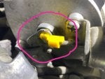
Here is teh pic...
![Image]()
![]()
here is the secong pic with longer shot...

i also want to know which way is open. is it open in the pic or closed?
Thx
Here is teh pic...
here is the secong pic with longer shot...